|
Sound characteristics of audio equipmentIn the audio market, we can find many related introductions of various equipments. Usually, they will describe the various characteristics in the equipment from the positive, and rarely explain the negative effects behind the characteristics. However, these negative factors control the quality on the music playback function. To get the sound effects you expect, you need to fully understand the equipment. In the following content, we will technically analyze what are the deficiencies in the equipment, what impact will it bring to the functional quality, and what sound characteristics will appear from this. We do not intend to evaluate the quality of the equipment, nor do we intend to impeach the defects of the equipment. Here is just to introduce the sound characteristics of these devices from the perspective of principles, so that when you use these devices, you can give full play to their strengths and avoid weaknesses. If necessary, you can quickly determine the location of the sound effect based on these characteristics. It must be known that, like everything else, audio equipment is not absolutely good or bad. In daily music appreciation, as long as the equipment can meet the sound effects you like, it is a good equipment for your sound system. Everything in the world should have an explanation, and the sound system is no exception. Audio equipment is a product of electronic technology, and its various phenomena must conform to physical principles and should be explained technically. In principle, all types of equipment have sound characteristics produced by their physical characteristics. Although each device of the same device has its own sound personality, the common characteristics of their device types will still exist. In the following, we will use the term micro-dynamics. Micro dynamics is the ratio of two voltage (or sound pressure) values in a time interval. In some cases, it is equivalent to what audio enthusiasts call micro-dynamics. The only difference is the length of the time interval. Generally, the minimum time interval for the human ear to confirm the existence of two sound pressure intensities (or there are two sounds) from the sound is 0.1 second. The micro dynamics we are referring to here include very short time intervals and extend to a range that can be distinguished by the human ear. We will also use the term "Sound State" in the following description. Sound State——The emotional state of the sound. Technical expression: The sound pressure value will change over time. This change relationship is expressed on the coordinate graph of the amplitude vertical axis and the time horizontal axis, which will produce a trajectory of the sound pressure value changing with time. Sound state-the shape of the track of sound pressure changes over time. In the product introduction, we will find some technical indicators related to the equipment. How will various indicators affect sound quality? How big is its impact? Which indicator has the greatest impact? This is a topic that audio enthusiasts often pay attention to and are discussed from time to time. The phase characteristics of the sound system will directly affect the sound state. Phase distortion will inevitably affect certain frequency components in music electrical signals, causing them to be misaligned on the time axis. This will change the instantaneous value of sound pressure at certain timing positions and will also produce micro-dynamic distortion in a short time interval. The various distortions of the sound system, they all change the signal waveform in the end, and specifically change the sound state and timbre. About
timbre Non-linear (harmonic) distortion will also cause some frequency components not in the original signal to appear on the signal spectrum, thereby changing the timbre of the sound. Unlike intermodulation distortion, the number of frequency components produced by nonlinear distortion has a linear relationship with the number of original signal frequency components, but the relationship reflected by intermodulation distortion is exponential (to be precise, it is called mathematically Combination relationship)). The meaning of the distortion
indicator Segmented circuits with nonlinear distortion will inevitably produce intermodulation distortion. A signal containing two or more frequency components, passing through a segmented circuit with nonlinear distortion, will inevitably have additional frequency components that the original signal does not have. Once these intermodulation distortion products appear, they cannot be separated or removed from the signal. Intermodulation distortion and nonlinear distortion are closely related, but they have different meanings. If the signal processed by the amplifier is a sine wave (only a single frequency component), the nonlinear distortion index has a certain meaning. If this is a music signal (contains two or more frequency components), the index of intermodulation distortion will be able to more fully reflect the overall characteristics of the amplifier. The technical indicators We can discuss this issue with an operational amplifier as an example. If op amps of the same company, the same model, different origins, or even the same model and different batches are installed on a typical audio circuit for testing. For some technical indicators currently used to measure audio equipment, we can all measure the same value. However, when we install these operational amplifiers on the same audio equipment for sound comparison, we will hear different sound effects. For audio equipment, the above example is a common phenomenon. It shows that these indicators are not enough to fully reflect the actual working quality of audio equipment. Many static indicators are used to measure audio equipment in industrial production. However, in addition to more directly reflecting the phase characteristics and intermodulation distortion of the sound quality of the audio equipment, most of the static indicators will gradually lose their meaning as the signal alternating speed increases and the dynamic increases. Therefore, based on the existing technical indicators, audiophiles may still be unable to effectively evaluate the actual quality of the equipment in actual use. Similarly, these indicators alone cannot effectively analyze the sound characteristics of audio equipment. Below, we will analyze the inevitability of the sound characteristics of the device based on physical principles (electronic principles obey physical mechanisms). Please note: When using a WRT cable, the sound characteristics described below can be accurately presented. If the audio system uses other cables, the sound state may be somewhat distorted, and the apparent degree of characteristics will vary. Grounding Amplifier * Low-frequency analog circuits used in audio equipment usually need some measures to filter out noise, overshoot, and high-frequency interference. Regardless of the original intention of adding these measures, they will correspondingly produce some negative effects of micro-dynamic filtering. The weak micro-dynamic filtering only reduces the sound details. When the intensity reaches a certain level and combined with loop feedback, these measures will produce an effect of compressing signal dynamics. Here, by the way, a frequently heard topic "Amplifier without Feedback". This feedback is of course negative feedback. Because positive feedback is the oscillator. We need to understand a simple concept: linear circuit. Linear circuits are also called analog circuits. The traditional amplifier is an analog amplifier. Now there is a digital amplifier in the audio market, that is, a class D amplifier. Analog amplifiers are also called feedback amplifiers or linear amplifiers. Because no device can have a completely linear amplification characteristic. To achieve linearity, the amplifier must introduce negative feedback. So any linear amplifier must be a feedback amplifier. Every amplifier design hopes to achieve a balance in the smoothness of the sound, the details of the music, the sense of speed, and the micro dynamics. Because power amplifiers need to drive complex inductive and capacitive loads, it is more difficult to satisfy this balance. Therefore, the design of some pre-amplifiers has increased the consideration of matching certain power amplifier characteristics to achieve this balance in the overall coordination of the system. Using this effectively, we can find many combinations of amplifiers that can be matched with each other. Preamplifier Later produced preamplifiers. As the signal source gradually becomes more single, the circuit structure of many preamplifiers is closer to the line amplifier in design. The circuit structure becomes simpler, combined with the improvement of component quality and technological progress, the timbre of the amplifier can be controlled more artificially. Therefore, there are more preamplifiers with various sound effects for us to choose from. Some preamplifiers are equipped with tone or working bandwidth control functions. These functions will change the phase characteristics of the amplifier, thereby changing the sound state. There are some passive volume controllers on the market that are used to replace preamplifiers. The use of such equipment will require: 1) High-quality signal interconnection lines, whose length should be as short as possible, especially the output end interconnection lines; 2) The receiving end equipment needs to have high input resistance and low input capacitance. However, most semiconductor devices do not have high input resistance; most vacuum tube devices do not have low input capacitance. Therefore, it will be more difficult for this type of equipment to get a perfect fit. If the above conditions are not met, after using this type of equipment, the frequency response and phase characteristics of the audio system will undergo considerable changes. Equalizer Power amplifier If we look at the speaker from another angle, we can think of it as a linear motion motor. In this way, we can further understand the importance of drive performance. Drive performance is related to the effectiveness of control. In many cases, the speaker's vibration system loses control, resulting in machine-like inertial vibration, which is considered to be the original low-frequency component of music. In fact, this is an example of poor driver performance. This type of sound is characterized by a single frequency as the main component, and maintains the same sound pressure amplitude in a short period of time. It is similar to acoustic resonance in a room, and we can easily recognize it from the sound of music. The drive performance is not necessarily related to the device type. But in this respect to achieve the same performance, different device types still have some differences. The tube amplifier has an output transformer, and its driving force is relatively weak due to obstruction. If the amplifier has a large internal resistance, when matched with a high-compliance speaker, there will be a longer period of under-driving. In addition, because the amplifier uses an output transformer, the change in speaker impedance will be equivalent to the power amplifier tube having a load that alternately changes between capacitive and inductive. This easily leads to phase distortion of the signal. Faced with these situations, the drive design of the tube power amplifier will encounter more difficulties. If vacuum tube amplifiers are required to have the same driving performance, their design also needs to solve their relatively more unfavorable factors. Any power amplifier with an output transformer must encounter the above-mentioned problems. Avoid using high-compliance speakers and choose speakers with relatively flat impedance characteristics, which can reduce their requirements for amplifier drive performance. This choice is equally valid for power amplifiers of any type of device. Drive performance is a technical topic. It refers to the ability of the amplifier to respond appropriately to the state to maintain its drive. This involves many aspects of control technology issues, which are not part of the content of this page and will not be discussed here. The advantage of the high-power output amplifier is that after matching with the speaker, the output of the amplifier can have a wider range to maintain excellent electrical/acoustic conversion linearity. However, this only makes sense when comparing products of the same brand and the same series. Different brands or different series of products may have different circuit structures or use different technologies. Its performance has been different, and there is no such inevitability. There is no absolute advantage in high-power output amplifiers. In the case of the same power output, the high-power amplifier will cause greater disturbance to the energy supply and cause greater interference to other devices. Adding power supply filter capacitors or modifying its internal power supply cannot effectively improve this interference. It needs to reduce the internal resistance of the power supply network to solve this problem. Find out how far the street grid transformer is from home, how many users the power supply line passes through, etc. These are all factors of the internal resistance of the grid and external interference. Certain power filters may also increase the internal resistance of the power supply network. In the case of the same internal resistance of the power grid, the interference of the full class A power amplifier to the power supply will be relatively small. Higher efficiency circuits will produce greater interference. Class A power amplifier Compared with the class AB power amplifier, the power tube of the class A power amplifier still needs to perform voltage swing under the high current state when the output is weak. Therefore, the speed of state changes will be relatively low (longer response time). This circuit has a strong micro-motion filter, and the sound is relatively smooth. The intensity of the micro-dynamic filtering of the semi-Class A power amplifier will increase with the increase of the depth of the Class A state. When it reaches a certain level, the original details of the music will gradually decrease. Full Class A power amplifiers have stronger micro-dynamic filtering. Due to the slower speed, the intermodulation distortion of the Class A power amplifier is larger. A small amount of intermodulation distortion products can change the timbre of the sound. As the number of frequency components of a music signal increases, the influence of intermodulation distortion increases. When playing some music with a wide frequency range (such as music played by a large orchestra), the sound will be messy. The degree of confusion is related to the overall phase characteristics of the audio system. Cross Distortion
For technical reasons, there is currently no amplifier with a conversion rate equal to infinity, and such amplifiers will not appear in the future. Under current technical conditions, the main problem of sine wave cross distortion is speed. On the contrary, when the output is weak, the state of the Class A power amplifier changes slowly, which is not conducive to improving the cross distortion of the sine wave. Therefore, the full class A power amplifier only has the characteristics of not turning off the power device. Not only can it not solve the problem of sine wave zero-crossing distortion, but it will also produce greater sine wave zero-crossing distortion under the same conditions. In addition, the non-turn-off feature allows the power device to withstand greater voltage swings. For existing power devices, this will have relatively poor linearity. In various test spectrograms, we can also see that the distortion of the Class A power amplifier is greater than the distortion of the Class AB power amplifier. Above, we have made some explanations on the formation mechanism of sine wave crossover distortion. The technical indicators of sine wave distortion are usually measured on audio equipment. However, the audio equipment handles music electrical signals in actual work. Therefore, if we want to accurately assess the substantial impact of various distortions of audio equipment on music playback, we need to discuss them in conjunction with the characteristics of music electrical signals. Tube
amplifier Regardless of whether the brand or model of the tube is the same, each tube has its own sound personality. However, the use of tubes to "play" sounds may only be suitable for preamplifiers. Because we rarely see the life of the power tube can exceed 2000 hours. After this time limit, its puberty will disappear, and the sound will change with the electrical characteristics of the tube. This is one of the biggest weaknesses of tube amplifiers. However, the Achilles heel of the tube amplifier does not lie in this. Such problems can be found in audio systems with high-resolution capabilities. When the amplifier is replaced with a tube, you may Hard to get back the sound effect you originally liked. The electron tube used in the preamplifier can have a relatively long life cycle, and some brands can reach 10,000 hours. However, they will gradually age without being noticed, and at the same time, their voices will change accordingly. Speaker Impedance Characteristic. In the effective working frequency range, no loudspeaker can have a horizontally flat impedance characteristic. After the speaker is connected to a power amplifier with an output transformer, the change in speaker impedance will cause micro-dynamic distortion of the amplifier. If the audio system uses a power amplifier with an output transformer, choosing a speaker with a relatively flat impedance characteristic curve will help reduce this distortion. Phase Characteristics. In the effective working frequency range, no loudspeaker can have horizontally flat phase characteristics. By adjusting the placement of the speakers, the phase characteristics can be corrected to a certain extent. A speaker with flat phase characteristics is more conducive to reproducing real sound, and its placement location can also have more choices. Frequency Response Characteristics. In the effective working frequency range, no loudspeaker can have a horizontally flat frequency response characteristic. Frequency response characteristics will affect the timbre of the sound, but this is different from the change in timbre caused by distortion. This effect will be linear. It is only equivalent to the personality difference of the same instrument but different timbre, and basically does not cause the change of the sound state. Speaker's
edge Compared with the rubber ring, the foam and cloth ring speakers have a smaller machine inertia, it is easier to obtain the cooperation of the power amplifier, and the probability of underdrive or overload is relatively low. Whether the loudspeaker will appear under-driving and over-driving, depends on the interaction between it and the amplifier. As the inertia of the vibration system increases, the speaker's requirements for amplifier drive performance also increase. Every time you use the speaker, you need to warm it up for a period of time before it can enter the linear working state. The loudspeaker has greater inertia and requires longer Warm-up time. Cable Interconnect Balanced or Single Ended Generally, as long as one of the two equipments processes the signal in a fully balanced manner, the effect of balanced transmission will be better. If the two equipments are single-ended processing signals, you need to consider factors such as the transmission distance of the signal, the functional quality of the conversion circuit, and the isolation design of the equipment. Therefore, the signal terminal selection in this case often needs to be compared on a specific equipment to distinguish the pros and cons of the signal connection. Speaker Cable Musical electrical signals have a wide frequency band (10 octaves). The power transmission of each frequency component has its own standing wave. And the respective standing wave amplitude will vary according to the electrical characteristics of each speaker. Combined with the real-time problem of the frequency spectrum, after the music electric signal is transmitted, the waveform changes of different speakers will be different, and the sound state will also be different. In this way, the speaker cable will inevitably become a special component that matches the personality of the speaker. For a specific speaker, using different cables, the sound will have different sound states. With this function, you can get your favorite sound effect relatively easily by changing the speaker cable. Power Cord Optical LP turntable To maintain accurate stylus pressure under dynamic (working) conditions, the strut mechanism of the vocal arm will play an important role. The arm strut mechanisms of different axial types have different following characteristics for the oscillating movement of the stylus, which specifically affects the timbre and sound state. The stylus pressure will change with environmental factors, such as temperature, humidity, air pressure, etc. The pressure scale on the tonearm can only be used as a reference, and it is difficult to rely on it to obtain accurate stylus pressure. For users of LP turntables, there may be an unexpected gain with an accurate stylus pressure gauge. RIAA Equalization (preset equalization) only has an agreement on the amplitude-frequency characteristics, but does not establish a specification for the phase characteristics. Different types of analog inverse equalization circuits have different phase characteristics. Therefore, different phono amplifiers may also have different phase characteristics. The phase characteristics will affect the sound state, however, this parameter usually does not appear on the product's technical indicators. MC Transformer Therefore, if the MC step-up transformer is used, you need to: 1) Minimize the input capacitance of the MM phono amplifier; 2) The output terminal interconnection line must be of low capacitance and shorten the length as much as possible. Regarding the first point, compared with semiconductors, electronic tube equipment generally has a larger input capacitance, so it is not easy to meet this requirement. Audio
CD CD Disk CD optical disc media has such characteristics, which puts forward more stringent requirements on CD players. Even so, if some high-quality CD discs are paired with a high-quality CD player, the sound quality will still be better than other audio sources. For example, XRCD has good sound effects on many HI-End players. The codes AAD, ADD, DDD marked on the CD disc not only indicate which stage of the technology is used in the music recording on the CD disc. Through these codes, we can also know whether the music signal on the CD is processed by an analog mixer. Analog mixer will affect the sound quality of music playback from the aspect of phase. The sound quality of an audio CD will not only be affected by burning and post-production, but the structural quality of the disc will also affect the accuracy of the data and ultimately affect the sound quality. The production process of some CD discs shortens the cooling time to increase productivity. As a result, the quality of the pit structure representing the data is reduced. The amount of jitter of CD disc data has also increased. We can distinguish these CD discs by simply observing the transmittance and uniformity of the reflective layer. CD discs with relatively thick and uniform reflective layers usually have a longer cooling time. They will always have better structural quality. D/A Converter The one-digit digital-to-analog chip has poor conversion accuracy and softer sound. One and multiple digital/analog hybrid chips are also used in recent CD players. The electrical characteristics of this type of chip are between one-bit and multi-bit chips, and are closer to multi-bit chips. CD players produced in later stages mostly use the above two types of chips. In the post-production of CD Transports, they used a more mature digital signal processor (DSP). These DSP chips include a 32Kbit CIRC decoder memory, which can process data faster, so there are more time resources to correct more data errors. The decoder with 8x digital filter and multi-bit digital/analog chip is used as an analog unit with post-production CD transmission. This method combined with a CD player can usually achieve higher detail density. External Clock Up-sampling SACD Compared with CD, SACD disc has a higher data storage density. Due to the use of plastic as the data carrier, data stream jitter is more difficult to control. Therefore, under the same technical conditions, SACD playback will be more prone to data errors. For 24bit/96KHz and DVD Audio digital music formats, because they also have a higher data storage density, they will also encounter this problem. About various coding formats Another topic of the same nature is the difference in sound quality between CD and LP. After the CD appeared, the discussion on this issue did not stop. Until today, thirty years later, LP is once again sought after by fans. This phenomenon only reflects the actual CD in use, and there is indeed a gap between sound quality and LP that cannot be underestimated. Just like the accuracy of emotional expression that is essential in music playback. Of course, if we regard music as language, the accuracy of its emotional expression is also very important. We also compared the sound of CD and LP. In our comparison, audio CD music playback has better performance. This is reflected in some singing performances. We can feel that singers have appropriate emotional expressions when performing works, and music can more accurately depict the artistic conception of lyrics. This is because CD has a technical foundation that provides more musical details. When the player gets the correct data, the sound quality of an audio CD is of course better than that of an LP record. However, this result cannot represent a general phenomenon. This is also because the quality of CD and LP sound quality and the degree of difference are also restricted by the conditions of whether the playback device can obtain the correct data. So our comparison result may be different from others. Data correctness As more and more data is generated, players need to have a higher speed to process the data. As the operating speed of the device increases, the frequency of the bit clock must be increased accordingly, that is, the cycle time of the bit clock will be shortened accordingly. Under the same technical conditions, as the period of the bit clock is shortened, the jitter of the bit clock relative to the period time will increase accordingly. At the same time, as the bit clock period is shortened, the jitter of the data stream relative to the bit clock period will increase accordingly. In other words, as the working speed of the equipment increases, the probability of data errors also increases. Analog signal accuracy High-frequency sampling will have a greater number of settling times, and the amount of error (the amount within the settling time period) will occupy more time space. Therefore, when the sampling frequency is increased to a certain extent, the time for the accurate value of the analog quantity is shortened, and the time for the error value is increased. That is, the proportion of analog signals containing errors increases. The influence of the settling time on the accuracy of the analog signal will subsequently reach a level that cannot be ignored. The above-mentioned problems are just some of the many shortcomings. They affect the sound quality of music playback in terms of data correctness. Although in theory, many digital music formats and sound quality enhancement modes have some advantages. However, due to various restrictions, they may not currently bring the expected results. There are some differences between ideals and reality, and it is necessary for our technicians to reduce these differences. CD disc data low-jitter processing Tai Chi backup is an improvement measure for audio CD data prone to errors in actual use. It is further confirmed that whether the playback device can obtain the correct data is the key to whether the advanced encoding format can exert its advantages. Created by:Chen All rights reserved by Chen Audio Laboratory, Inc. |
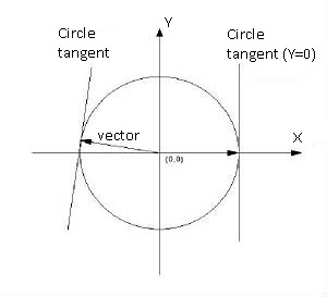 Why is sine wave crossover distortion a problem that cannot be completely solved? This is a basic topic. We need
to explain from the formation of sine waves. In the Cartesian coordinate system, the vector whose starting point falls on
the coordinate origin (0, 0), takes the starting point as a fixed point, and performs circular motion at a constant angular
velocity. In motion, the magnitude of the end point of the vector on the Y axis (the horizontal projection of the end point
of the vector on the Y axis) is the amplitude of the sine wave corresponding to a certain radian. At the zero crossing point
(Y equals 0) of the sine wave, the circle tangent is orthogonal to the X axis. The circle tangent is the slew rate of the
sine wave trace. The tangent of the circle at the zero crossing point is a vertical line, which means: the sine wave has an
infinite slew rate at the zero crossing point. Regardless of the frequency of the sine wave, the situation where the slew
rate is equal to infinity at the zero-crossing point will not change.
Why is sine wave crossover distortion a problem that cannot be completely solved? This is a basic topic. We need
to explain from the formation of sine waves. In the Cartesian coordinate system, the vector whose starting point falls on
the coordinate origin (0, 0), takes the starting point as a fixed point, and performs circular motion at a constant angular
velocity. In motion, the magnitude of the end point of the vector on the Y axis (the horizontal projection of the end point
of the vector on the Y axis) is the amplitude of the sine wave corresponding to a certain radian. At the zero crossing point
(Y equals 0) of the sine wave, the circle tangent is orthogonal to the X axis. The circle tangent is the slew rate of the
sine wave trace. The tangent of the circle at the zero crossing point is a vertical line, which means: the sine wave has an
infinite slew rate at the zero crossing point. Regardless of the frequency of the sine wave, the situation where the slew
rate is equal to infinity at the zero-crossing point will not change.